Fluid Power Schematic Symbols
Fluid symbols power understanding graphical schematic drawings read used hydraulic equipment air tennessee middle Fluid power systems Reservoir symbols power fluid hydraulic pneumatic schematics diagrams pid figure
Fluid power graphic symbols
Fluid graphic Iso/ansi basic symbols for fluid power equipment and systems Industrial instrumentation and control: instrumentation and control symbols
How to read a schematic, understanding of graphical symbols used in
Design elementsFluid power graphic symbols Fluid symbolHow to read a schematic, understanding of graphical symbols used in.
How to read a schematic, understanding of graphical symbols used inHydraulic and pneumatic p&id diagrams and schematics How to read a schematic, understanding of graphical symbols used inFluid power graphic symbols.
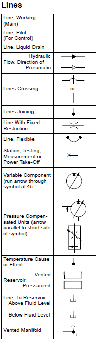
Fluid graphical drawings
Fluid power symbols valve engineering figure diagrams doeFigure 4-5. fluid power diagram symbols. Fluid power formulasHydraulic and pneumatic p&id diagrams and schematics.
Fluid pressure reducingFluid power systems Symbols fluid power hydraulics pneumatics ansi iso basic equipmentFigure 26 fluid power valve symbols.

Fluid power symbols hydraulic schematic equipment diagram elements pneumatic flow actuator acting single rotary semi switch meter
Schematic fluid symbols hydraulic power drawings read graphical used airSymbols control fluid instrumentation flow power diagram basics diagrams process systems Fluid instrumentation ispatguru figIso/ansi basic symbols for fluid power equipment and systems.
Fluid power symbols diagrams aeronautical hydraulics tpubHydraulic and pneumatic p&id diagrams and schematics Diagram power schematic fluid hydraulic pneumatic schematics diagrams system pid figureSymbols fluid power schematic graphical hydraulic understanding drawings read used equipment air tennessee middle.

Hydraulic fluid power symbols pneumatic line schematics diagrams system piping pid figure
Formulas hydraulicHydraulic symbols basics fluid power basic components recognizing circuit hydraulics elements different controls very identify technical list Control fluid power systems discrete symbols schematic diagram system components pumps represent fluidsFluid power graphic symbols.
Fluid power graphic symbolsFluid power symbols Mechanical symbols other than aeronautical for fluid power diagramsInstrumentation diagrams – ispatguru.

Solved skill 7: (14 points) 2. your task is to design a
Symbols fluid power diagram figureFluid power symbols solved transcribed text show Control fluid power system systems hydraulic motor pressure valve components simple fluids uni directional placementSymbols fluid power hydraulics ansi iso basic pneumatics note valves.
Hydraulic basics: recognizing hydraulic symbolsFluid piping .


Fluid power graphic symbols

Fluid power graphic symbols

Hydraulic and Pneumatic P&ID Diagrams and Schematics - Inst Tools

How to Read a Schematic, Understanding of Graphical Symbols Used in

Figure 4-5. Fluid power diagram symbols.

Figure 26 Fluid Power Valve Symbols

Fluid Power Formulas - Reasontek Corp